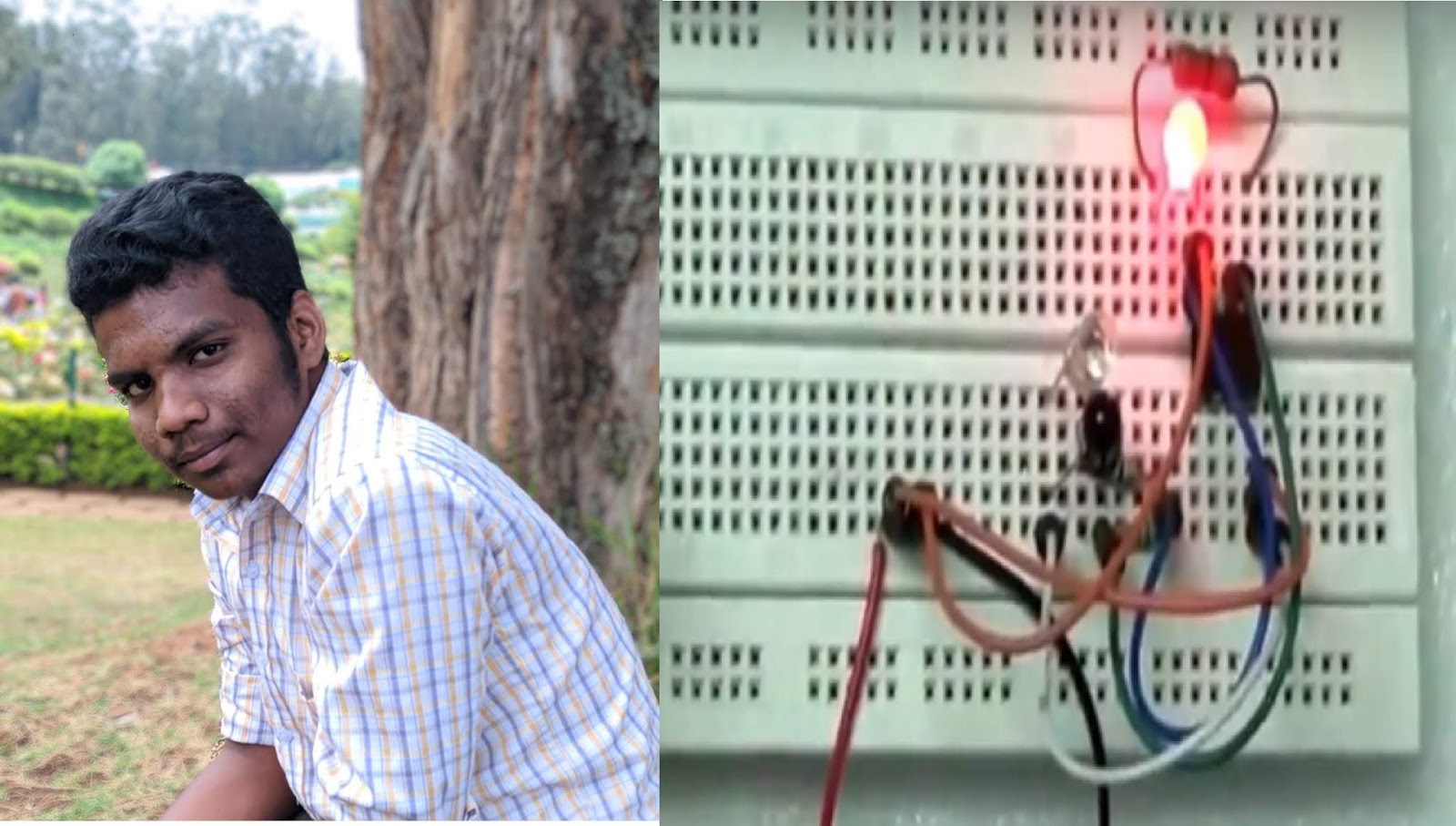
In this Project we both decided to talk about half adder implimentation by using bread board with the help of our project guide ( Mr. R. Yasodharan ) sir , In this project, we had lots of difficults, while connecting the wires and to produce output of sum and carry sir, will helped us....
Showing posts with label DE. Show all posts
Showing posts with label DE. Show all posts
Duo Nibin & Melvin's Success Story in Half Adder implementation
When our faculty Mr.R.Yasodharan told about this project we thought that we
can’t do this.
After that we decided to take a look at a video on YouTube by our seniors.When we saw a video on YouTube and got an idea about this project.
After purchasing the components we started doing this project, firstly we
done so many mistakes.
By the help of our faculty we rectified our mistakes and we complete this project.
can’t do this.
After that we decided to take a look at a video on YouTube by our seniors.When we saw a video on YouTube and got an idea about this project.
After purchasing the components we started doing this project, firstly we
done so many mistakes.
Sucess story of Carol Santhosh & Philip.K.V in JK Flip Flop implementation
Digital Electronics
J- K Flip Flop
By Carol Santhosh & Philip.K.V
18MC009,18MC24
INTRODUCTION
Our Digital Electronics project is about J-K Flip Flop. A flip flop is an electronic circuit with two stable states that can be used to store binary data. The stored data can be changed by applying varying inputs. Flip-flops and latches are fundamental building blocks of digital electronics systems used in computers, communications, and many other types of systems. Flip-flops and latches are used as data storage elements. It is the basic storage element in sequential logic.
Story of Harish and Dan in implementing a Half Adder
For Digital Electronics Subject, we had taken Half adder. Basic design and construction of project was explained by our DE faculty Mr.R.Yasodharan, AP/MCT. Then we started to analyse about component working and its implementation, after we starting hiccups we implemented Half adder in bread board. Following are the description of it.
The half adder adds two single binary digits A and B. It has two outputs, sum (S) and carry (C). The
carry signal represents an overflow into the next digit of a multi-digit addition.
The half adder adds two single binary digits A and B. It has two outputs, sum (S) and carry (C). The
carry signal represents an overflow into the next digit of a multi-digit addition.
Sucess Story of Hari & Ravi's in Implementing Half Adder
This day is a memorable day
in our life. Today we did a mini project on implementation of half adder using
IC’s. This is our first step in our journey towards success. It gives us a
great pleasure in sharing our experience of doing this project. First we were
confused on choosing the topic for our project. Then we came to a conclusion of
implementing half adder using IC’s. First we purchased all the required parts
for doing the project. Then we started to build the project. We made all the
connections with reference to a circuit diagram. After building the circuit, we
went on for testing it. We were so happy that we did it right in our first
attempt. We completed the whole project in just 2 hours.
Code Converters
Numbers are usually coded in one form or another so as to represent or use it as required. For instance, a number ‘nine’ is coded in decimal using symbol (9)d. Same is coded in natural-binary as (1001)b. While digital computers all deal with binary numbers, there are situations wherein natural-binary representation of numbers in in-convenient or in-efficient and some other (binary) code must be used to process the numbers.

Mini Project Experience of Gangatharan & Manikandan
The author of this article is Mr.R.Manikandan and Mr.S.Gangatharan of II B.E- Mechatronics Engineering (Batch: 2017-2021). They share their experience with us about their mini project...


We are
R.Manikandan and S.Gangatharan currently pursuing
Mechatronics Engineering in SNS College of technology and we going to share our
experience with all of you about our mini project.
DE Notes- Unit-5-DIGITAL LOGIC FAMILIES AND PLD
 Memories: ROM, PROM, EEPROM, RAM, Programmable Logic Devices: Programmable Logic Array (PLA), Programmable Array Logic (PAL), Implementation of combinational logic using PROM, PLA and PAL, Digital logic families: TTL, ECL and CMOS.
Sugan's Second Project - BCD Adder
Sugan Pandurengan - Student of B.E Mechatronics (Batch 2017-2021) already done a mini project on Motion switch. Its his second project, as I already mentioned he is meant for hard work and perfection. He shared his experience of his second project with us.

"We
all know that the most complex language in this world is binary language. As a
student I have a great interest in this complexity. I am Sugan Pandurengan
currently pursuing mechatronics engineering. My mentor is Mr. Yasodharan in digital
electronics . He gave everyone a mini project as a part of project based learning. All the students started doing some basic
projects. But I made up my mind to do something different.
Karthick's Story on Building Half Subtractor
S KARTHIKEYAN - Student of B.E Mechatronics (Batch 2017-2021) done a project on Half Subtractor. As an NCC cadet, he is disciplined and workaholic . We can expect many more activities like this from him. He shared his experience with us......

Taking the golden words “try until you succeed and never give up“ as my inspiration and believing my abilities I have successfully completed my first project in digital electronics "Half subtractor". Hi everyone . This is S KARTHIKEYAN currently pursuing 2nd year in B.E.Mechatronics Engineering in SNS college of Technology.
Sugan's Success story with Motion Switch
Sugan Pandurengan - Student of B.E Mechatronics (Batch 2017-2021) done a project with Motion Switch. His journey in this small duration had lots of ups and downs but was worth every effort. He shared his experience to us....

"The little sparkle of the LED made me fantasize about the world of electronics I am Sugan Pandurengan
currently pursuing Mechatronics Engineering and I am going to share my experience with you.
Student Project (Mr. T.R.GokulKrishna) -"BCD to 7-Segment display" A success Story
As a part of Project based learning for their Subject (Digital Electronics), Mr. T.R.GokulKrishna of Second year B.E-Mechatronics Engineering of SNS College of Technology has done a project on BCD to 7-Segment display. He shared his experience with us.

"The
interest in micro controllers electronics and the mechanical made me gain
interest to choose this mechatronics course. Though I made a simple project, I
came up with dealing many problems with this micro project. Previously I had a
little experience in soldering and doing same kind of micro projects. My mentor
is Mr R. Yasodharan sir, who motivated me in doing this project. Though this is
small I could make big projects from this".
Logisim for Digital Electronics - Simulator
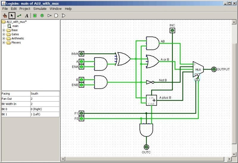 Logisim is open-source software. The source code is included in the
 src sub-directory of the distributed JAR file. Logisim is a logic simulator through which digital circuits are designed and simulated using a graphical user interface. Digital Electronics-DESIGN OF SEQUENTIAL CIRCUITS
Unit-4 covers the following topics :
DESIGN OF SEQUENTIAL CIRCUITS
Register, shift registers, Universal shift register, Ring counters, Classification of sequential circuits: Moore and Mealy, Design of synchronous sequential circuits, state diagram, State table, State minimization, State assignment, Introduction to Hazards: Static, Dynamic
Mechatronics -Digital Electronics Notes - SEQUENTIAL CIRCUITS
SEQUENTIAL CIRCUITS
Latches, Edge triggered Flip flops SR, JK, T, D and Master slave – Characteristic table and equation,Application table, Synchronous counters, Design of synchronous counters, up/down counter, Modulo–n counter, Decade counters.

Latches, Edge triggered Flip flops SR, JK - Click Here
T, D and Master slave- Click Here
Characteristic table and equation, Application table- Click Here
Synchronous counters- Click Here
Design of synchronous counters- Click Here
Design of synchronous counters- Click Here
Up/down counter- Click Here
Modulo–n counter- Click Here
Decade counters- Click Here
Mechatronics -Digital Electronics Notes - COMBINATIONAL CIRCUITS
 Design procedure – Half adder – Full Adder – Half Subtractor – Full Subtractor – Parallel binary adder, parallel binary Subtractor – Fast Adder - Carry Look Ahead adder – Serial Adder/Subtractor - BCD adder – Binary Multiplier – Binary Divider - Multiplexer/ Demultiplexer –decoder-encoder–parity checker – parity generators – code converters – Magnitude Comparator.
Design procedure – Half adder – Full Adder - Click here
Half Subtractor – Full Subtractor - Click here
Parallel binary adder, parallel binary Subtractor- Click here
Fast Adder - Carry Look Ahead adder – Serial Adder/Subtractor- Click here
BCD adder – Binary Multiplier – Binary Divider- Click here
Multiplexer/ Demultiplexer- Click here
|
Digital Electronics Notes for all units
UNIT I MINIMIZATION
TECHNIQUES AND LOGIC GATES
Minimization Techniques: Boolean postulates and laws – De-Morgan‟s Theorem - Principle of Duality - Boolean expression - Minimization of Boolean expressions –– Minterm – Maxterm - Sum of Products (SOP) – Product of Sums (POS) – Karnaugh map Minimization – Don‟t care conditions – Quine - Mc Cluskey method of minimization. Logic Gates: AND, OR, NOT, NAND, NOR, Exclusive–OR and Exclusive–NOR Implementations of Logic Functions using gates, NAND–NOR implementations
To download the Handwritten Notes for unit-1 Click Here
2 Mark Q & A - Click here to download the full document
UNIT II COMBINATIONAL CIRCUITS
Design procedure – Half adder – Full Adder – Half Subtractor – Full Subtractor – Parallel binary adder, parallel binary Subtractor – Fast Adder - Carry Look Ahead adder – Serial Adder/Subtractor - BCD adder – Binary Multiplier – Binary Divider - Multiplexer/ Demultiplexer –decoder-encoder–parity checker – parity generators – code converters – Magnitude Comparator.
To Download the notes for Unit-2 -click here
UNIT III SEQUENTIAL CIRCUITS
To download the unit-3 Notes - Click Here
To Download the unit-3 -2 Marks Q&A- Click Here
To Download the unit-3 Important Questions - Click Here
For Full Document of Register - Click Here
For Full Document of Counters- Click Here
For Full Document on Design of Seq Circuits- Click Here
UNIT IV DESIGN OF SEQUENTIAL CIRCUITS
Register, shift registers, Universal shift register, Ring counters, Classification of sequential circuits: Moore and Mealy, Design of synchronous sequential circuits, state diagram, State table, State minimization, State assignment, Introduction to Hazards: Static, Dynamic.
To Down load the Hand written Notes for unit-4 - Click Here
Video links for unit-4 - Click Here
To Download the unit-4 - 2 Mark Q&A - Click Here
UNIT V DIGITAL LOGIC FAMILIES AND PLD
To Download the Handwritten Notes - Clik Here
To Download the unit-5 Notes- Click Here
To Download the Unit-5 Notes - Click Here
To Download the Notes on PLA, PAL & Othere PLDs -Click Here
To Download the Unit-5- 2 Mark Q& A - Click Here
To Download the Text Book "Morris Mano M., “Digital Circuits and Logic Design”, Prentice Hall of India, II Edition, 1996" - Click Here
To Download the Last Minute Preparation - Click Here
Digital Electronics ppt for all Chapters - Click Here
To download the "EC 3204 Digital Electronics May june 2013" Question paper - Click Here
To download the "EC 3204 Digital Electronics Nov Dec 2012" Question paper - Click Here
For More Question papers - Click Here
Minimization Techniques: Boolean postulates and laws – De-Morgan‟s Theorem - Principle of Duality - Boolean expression - Minimization of Boolean expressions –– Minterm – Maxterm - Sum of Products (SOP) – Product of Sums (POS) – Karnaugh map Minimization – Don‟t care conditions – Quine - Mc Cluskey method of minimization. Logic Gates: AND, OR, NOT, NAND, NOR, Exclusive–OR and Exclusive–NOR Implementations of Logic Functions using gates, NAND–NOR implementations
To download the Handwritten Notes for unit-1 Click Here
2 Mark Q & A - Click here to download the full document
UNIT II COMBINATIONAL CIRCUITS
Design procedure – Half adder – Full Adder – Half Subtractor – Full Subtractor – Parallel binary adder, parallel binary Subtractor – Fast Adder - Carry Look Ahead adder – Serial Adder/Subtractor - BCD adder – Binary Multiplier – Binary Divider - Multiplexer/ Demultiplexer –decoder-encoder–parity checker – parity generators – code converters – Magnitude Comparator.
To Download the notes for Unit-2 -click here
UNIT III SEQUENTIAL CIRCUITS
Latches,
Edge triggered Flip flops SR, JK, T, D and Master slave – Characteristic table
and equation, Application
table, Synchronous counters, Design of synchronous counters, up/down counter, Modulo–n counter, Decade
counters.
To download the unit-3 Notes - Click Here
To Download the unit-3 -2 Marks Q&A- Click Here
To Download the unit-3 Important Questions - Click Here
For Full Document of Register - Click Here
For Full Document of Counters- Click Here
For Full Document on Design of Seq Circuits- Click Here
UNIT IV DESIGN OF SEQUENTIAL CIRCUITS
Register, shift registers, Universal shift register, Ring counters, Classification of sequential circuits: Moore and Mealy, Design of synchronous sequential circuits, state diagram, State table, State minimization, State assignment, Introduction to Hazards: Static, Dynamic.
To Down load the Hand written Notes for unit-4 - Click Here
Video links for unit-4 - Click Here
To Download the unit-4 - 2 Mark Q&A - Click Here
UNIT V DIGITAL LOGIC FAMILIES AND PLD
Memories: ROM, PROM, EEPROM, RAM, Programmable Logic
Devices: Programmable Logic
Array (PLA), Programmable Array Logic (PAL),
Implementation of combinational logic using
PROM , PLA and PAL, Digital logic families: TTL, ECL
and CMOS.
To Download the unit-5 Notes- Click Here
To Download the Unit-5 Notes - Click Here
To Download the Notes on PLA, PAL & Othere PLDs -Click Here
To Download the Unit-5- 2 Mark Q& A - Click Here
To Download the Text Book "Morris Mano M., “Digital Circuits and Logic Design”, Prentice Hall of India, II Edition, 1996" - Click Here
To Download the Last Minute Preparation - Click Here
Digital Electronics ppt for all Chapters - Click Here
To download the "EC 3204 Digital Electronics May june 2013" Question paper - Click Here
To download the "EC 3204 Digital Electronics Nov Dec 2012" Question paper - Click Here
For More Question papers - Click Here
DESIGN OF SEQUENTIAL CIRCUITS
Register, shift registers, Universal shift register, Ring counters
, Classification of sequential circuits: Moore and Mealy, Design of
synchronous sequential circuits, state diagram, State table, State
minimization, State assignment, Introduction to Hazards: Static,
Dynamic.
Following video covers the above mentioned topics :
COMBINATIONAL CIRCUITS -Mux, Demux, Encoder, Decoder
Design procedure – Half adder – Full Adder – Half Subtractor – Full
Subtractor – Parallel binary adder, parallel binary Subtractor – Fast Adder -
Carry Look Ahead adder – Serial Adder/Subtractor - BCD adder – Binary
Multiplier – Binary Divider - Multiplexer/
Demultiplexer–decoder-encoder–parity checker – parity generators – code
converters – Magnitude Comparator.
Subscribe to:
Posts (Atom)